Integrate cameras with AI models at the edge
This tutorial describes how you can deploy an example application that integrates cameras with vision-based ML models. You can deploy the example as a standalone application or as a component of the Vision AI Edge solution.
The solution walks you through the following steps:
- Install the camera client application.
- Discover or configures cameras using different protocols.
- Trigger inference with messages or user action.
- Forward camera frames to the ML models.
- Provide inference results on local network.
- Collect training images for model training.
- Optionally stream inference results to BigQuery.
Architecture diagram

Costs
This tutorial uses billable components of Google Cloud, including the following:
Use the pricing calculator to generate a cost estimate based on your projected usage.
Before you begin
This tutorial assumes that you already have a Google Cloud account set up.
Create a Google Cloud project
- Go to the Cloud Console.
- Click the project selector in the upper-left corner and select New Project.
- Give the project a name and click Create.
- Click the project selector again and select your new project.
Supported camera types
Make sure you're using one of the following camera types:
- Genicam / GigE Vision IP cameras.
- RTSP with ONVIF support, or simple RTSP IP cameras.
- USB cameras.
- File, as in using image files as source data.
Installation
You can deploy this solution either as part of the Vision AI Edge solution, or as a standalone component.
Installation as part of Vision AI Edge solution
If you wish to deploy the complete Vision AI Edge solution, please refer to its documentation as the primary guide.
Standalone Installation
To deploy the camera client, do the following steps:
-
On your local development machine, install the following tools:
-
Configure
gcloudto use your new Google Cloud project: -
Export an environment variable with your current Google Cloud project ID:
-
Clone the repository and change to its directory.
git clone https://github.com/GoogleCloudPlatform/cloud-solutions/tree/main/projects/vision-ai-edge-camera-client \
&& cd projects/vision-ai-edge-camera-client
Note
It is recommended to use venv or pyenv virtualenv to create an isolated environment for this application and its imported modules. Please refer to the links in this step for more information on virtual environments.
-
Install dependencies:
-
Initialize your application default credentials:
Execute the following command to authenticate your shell with the Google Cloud project in use:
-
Build the container image that contains the camera client:
Execute the following to build the camera client image:
-
Run the camera client as a pod.
If you have deployed the camera client as part of the Vision AI Edge solution that solution deployes the camera client pods into Kubernetes. To run the camera client as a standalone container, you can execute:
The above command runs the camera client and opens a shell in the pod for executing the steps in the next chapters. You should see a prompt similar to this:
Note
The rest of the documentation assumes that the camera client is deployed as part of Vision AI Edge solution. The command examples in the following chapters use
kubectlfor Kubernetes. If you use this solution standalone, you can use equivalentdockercommands instead.In the next chapter, we connect to a camera as the data source. Use the chapter that matches your camera's connectivity protocol.
-
Print the camera client's command-line switches:
kubectl exec -it camera-integration -n ${NAMESPACE} -- /bin/bash \
-c 'python3 camera_client.py --help'
or if you have a shell open in the pod, execute:
Output is similar to the following:
usage: camera_client.py [-h] [--log {debug,info,warning,error,critical}]
                        [--protocol {genicam,onvif,rtsp,usb,file}]
                        [--device_id DEVICE_ID] [--address ADDRESS]
                        [--cam_user CAM_USER] [--cam_passwd CAM_PASSWD]
                        [--gentl GENTL]
                        [--background_acquisition BACKGROUND_ACQUISITION]
                        [--mode {none,single,continuous,interactive,mqtt_sub,batch}]
                        [--width WIDTH] [--height HEIGHT] [--count COUNT]
                        [--sleep SLEEP] [--pubsub {none,results}]
                        [--topic_id TOPIC_ID] [--ml] [--raw_write]
                        [--raw_write_path RAW_WRITE_PATH] [--img_write]
                        [--img_write_path IMG_WRITE_PATH] [--cfg_read]
                        [--cfg_read_file CFG_READ_FILE] [--cfg_write]
                        [--cfg_write_file CFG_WRITE_FILE]
                        [--temp_format {K,C,F}] [--range_min RANGE_MIN]
                        [--range_max RANGE_MAX] [--cloud_region CLOUD_REGION]
                        [--project_id PROJECT_ID] [--credentials CREDENTIALS]
                        [--ml_host ML_HOST] [--ml_port ML_PORT] [--ml_write]
                        [--ml_write_path ML_WRITE_PATH] [--mqtt]
                        [--mqtt_host MQTT_HOST] [--mqtt_port MQTT_PORT]
                        [--mqtt_topic_commands MQTT_TOPIC_COMMANDS]
                        [--mqtt_topic_results MQTT_TOPIC_RESULTS]
                        [--health_check] [--stdout {none,print,protobuf}]
                        [--scan] [--stream_delay STREAM_DELAY]
                        [--crop_left CROP_LEFT] [--crop_top CROP_TOP]
                        [--crop_right CROP_RIGHT] [--crop_bottom CROP_BOTTOM]
                        [--client_cfg_file CLIENT_CFG_FILE]
Connect Cameras
Connect Genicam cameras
If you are using a camera that supports the Genicam standard, do the following:
Ensure that the Genicam camera is connected to the same subnet as your host computer, using a gigabit ethernet PoE (Power over Ethernet) cable.
To communicate with the camera, you need to have its
GenTL producer file, with a .cti file ending, and the file
should be compiled for Linux x86-64. To use your camera’s GenTL producer file,
place it in a directory on the server that the pod can access. The directory
should be mounted in a persistent volume. This is done automatically by the
Vision AI Edge solution deployment.
Scan for Genicam cameras
Now that you have the GenTL producer file, you can scan for Genicam-based cameras on the local network segment.
-
Connect your camera to the same LAN segment as the server, using its Power over Ethernet (PoE) cable with a LAN cable from the same switch as the server. Ensure that the camera is powered on.
-
Inside the container shell, run the following command to scan for camera:
The output should be similar to this:
Discovering Genicam cameras on the network..
Genicam cameras found: [{'access_status': 1, 'display_name': 'FLIR Systems AB', 'id_': '00111C0242D4_C0A8011F_FFFFFF00_C0A80101', 'model': 'FLIR AX5', 'parent': <genicam.gentl.Interface;
proxy of <Swig Object of type 'std::shared_ptr< GenTLCpp::TLInterface > *' at 0x7fc4b54c9b70> >, 'serial_number': '62501484', 'tl_type': 'GEV', 'user_defined_name': '', 'vendor': 'FLIR Systems AB', 'version': 'Version 1.0  (02.05.15)'}]
In the above example, you can see that 1 camera was found, and the model is a
FLIR AX5. If your system can see multiple cameras, you can select which camera
to connect to, by using the --address switch, counting up from zero. Meaning
that if the command lists 2 cameras for example, the first listed camera is
--address 0 and the second camera is --address 1.
The camera client can currently only connect to one camera at a time. See the chapter called "Using multiple cameras with dedicated ML models" on how to scale the solution with multiple cameras and ML models.
Connect to the camera and read its runtime configuration
In this section you connect to the camera, read its current runtime
configuration (GenTL node tree), and output it to a configuration file that you
can edit. Later on, you can write the edited, desired configurations back to
the camera. The mode switch --mode none instructs the utility not to take
any images with the camera.
-
Query the camera configurations and output them to a file (replace the
device_idandgetnlpath with your own values).python3 camera_client.py \ --protocol genicam \ --address 0 \ --device_id cam1 \ --gentl /var/lib/viai/camera-config/<your-camera>.cti \ --mode none \ --cfg_read --cfg_read_file /var/lib/viai/camera-config/current.cfgThe output should look similar to this:
Cameras found: 1 (id_='00111C0242D4_C0A80019_FFFFFF00_C0A80001', vendor='FLIR Systems AB', model='FLIR AX5', tl_type='GEV', user_defined_name=None, serial_number='62501484', version='Version 1.0 (02.05.15)') Querying camera runtime configs and saving to: /var/lib/viai/camera-config/current.cfg Closing camera connection and exiting -
Verify the generated camera configuration file.
The output should be similar to this:
At this point, the camera is connected and ready to use. Optionally, you can continue reading to understand how to manage the configuration of a Genicam camera:
Manage the configuration of Genicam cameras
-
Query the camera's current runtime configurations and output them to an editable text file (replace
device_idandgentlpath with your own values). -
Verify the generated camera configuration file.
The output should be similar to:
-
To change a configuration parameter value, edit the generated configuration file.
-
Write the updated configurations back to the camera.
python3 camera_client.py \
--protocol genicam \
--address 0 \
--device_id cam1 \
--gentl <your camera gentl>.cti \
--mode none \
--cfg_write \
--cfg_write_file /var/lib/viai/camera-config/current.cfg
The output should be similar to:
At this point you can start to collect images for training in the next section.
Connect ONVIF-enabled RTSP cameras
Prepare your camera
Install and configure your IP camera using its management tools and ensure that:
- You have enabled ONVIF for remote management and discovery.
- The camera provides at least one RTSP stream URL.
- The camera is located in the same IP LAN segment as the server. ONVIF discovery uses broadcast messages which are not routed between LAN subnets.
Scan for ONVIF cameras
-
Open a shell to the camera client pod:
-
Scan the local LAN segment for any ONVIF-enabled cameras.
Note
The network scan uses the WSDiscovery protocol, which sends broadcast messages to discover devices. Next the utility tries to query all found ONVIF cameras, using the ONVIF protocol, and get their RTSP stream addresses.
If your camera has access control enabled using a username/password pair, you need to provide these credentials to enable the ONVIF query for RTSP streams information.
-
For unauthenticated cameras, run:
-
For cameras with authentication enabled, run:
The output should be similar to:
Discovering ONVIF cameras on the network..
ONVIF cameras found: [{'uuid': '2419d68a-2dd2-21b2-a205-ec', 'addr': '192.168.1.105', 'port': '8000'}]
Querying found ONVIF cameras for RTSP URIs..
ONVIF RTSP addresses found: ['rtsp://192.168.1.105:554/h264Preview_01_main', 'rtsp://192.168.1.105:554/h264Preview_01_sub']
The example above shows two camera streams discovered.
-
At this point you can start to collect images for training in the next section.
Connect simple RTSP cameras
You can't discover simple RTSP cameras automatically.
If your IP camera does not support ONVIF, you need to find its RTSP addresses manually, including a username/password pair if authentication is enabled. Use the RTSP stream information in the next chapters.
At this point you can start to collect images for training in the next section.
Connect USB cameras
The camera utility can discover USB cameras which are directly connected to a USB port on the host server.
In practice, the software scans the linux OS for video devices from
/dev/video0 until /dev/video9, i.e the first 10 connected USB devices.
If a device exists, the utility tries to open the device as a camera. If this works, it’s reported as an available camera.
Scan for USB cameras
-
On the server host OS side, use the
v2l4tool to check if the camera is connected and detected.The output should be similar to this:
Note
Depending on your server, you might have to reboot with the USB camera connected. In some instances, hot plug does not work correctly.
-
Open a shell to the camera client pod.
-
Within the pod, scan the local server for USB cameras.
The output should be similar to this:
The example above shows a valid camera connected to /dev/video0.
Manage the configuration of USB cameras
Optionally, you can continue reading to understand how to manage the configuration of a USB camera:
-
Query the camera's current runtime configurations and output them to an editable text file (replace the device address with your value, usually
/dev/video0).python3 camera_client.py \ --protocol usb \ --address /dev/video0 \ --device_id cam1 \ --mode none \ --cfg_read --cfg_read_file /var/lib/viai/camera-config/current.cfg 2>/dev/nullThe output should be similar to:
-
Verify the generated camera configuration file.
The output should be similar to:
-
To change a configuration parameter value, edit the generated configuration file.
-
Write the updated configuration back to the camera.
python3 camera_client.py \
--protocol usb \
--address /dev/video0 \
--device_id cam1 \
--mode none \
--cfg_write --cfg_write_file /var/lib/viai/camera-config/current.cfg 2>/dev/null
The output should be similar to this:
At this point you can start to collect images for training in the next section.
Use image files as a data source
The camera client can also use image files as the source data for ML inference. This can be useful if the camera system is external to this server, and the two cannot be integrated directly.
In this scenario, a local integration is required to take images on the external camera system and then copy the image files to the server hosting this solution.
Note that the image files need to be on a filesystem that is accessible to the
camera client container. In practice, the best place to copy the images is
the kubernetes volume mounted as /var/lib/viai/camera-data in the pod.
When you have transferred an image, you can use it as the inference source 'camera' following these steps:
-
Open a shell to the camera client pod.
-
Run the camera client, using the image file copied earlier as the data source. In this example, the ML model is hosted at the address exported as
$ML_HOST. See the next chapters to learn more about running ML models.export ML_HOST=<ml-model-address> export ML_PORT=<ml-service-port> python3 camera_client.py \ --protocol file \ --address /var/lib/viai/camera-data/source-image.png \ --device_id 'filecam' \ --mode single \ --ml \ --ml_host ${ML_HOST} \ --ml_port ${ML_PORT} --client_cfg_file client.cfgThe switches
--ml,--ml_host,--ml_portand--client_cfg_fileare explained in the chapters that follow. The above example is just to show how to use files instead of a real camera, with--protocol fileand the-address <file_path>switches.
At this point you can start to collect images for training in the next section.
Collect and upload training images
This chapter discusses collecting training images for defect detection models. However, the general principles are the same for other types of vision-based ML models' training.
Collect training images
To create a custom ML model we need to collect training images forrom your particular use case. The images are acquired from the camera and written on disk on the edge server, from where they are uploaded to Google Cloud Storage. Once the images are in GCS, they can be used as source data for training pipelines.
Prepare to collect the training images
This step is highly use-case specific. You create an appropriate environment where you can use the camera connected to the edge server to take images of both normal, and abnormal situations for the products to be inspected.
Here are some general principles:
- Set up a controlled test environment which minimizes external influences such as ambient light affecting the camera exposure.
- Place the camera in its intended position. Take single shots to verify that the camera can fully see the objects to be inspected and not much extra space beyond them, to maximize the number of pixels covering the objects. Adjust the camera exposure, focus, focal length etc parameters and lock them in place, to avoid auto-adjustments changing the settings between shots.
- Ensure that the camera does not move or shake when taking pictures.
- Ensure that the objects do not move, or move too fast when taking the images, resulting in motion blur or rolling shutter effects.
- Setup consistent, even lighting and eliminate variable ambient light sources such as open windows nearby.
Upload training images
Use the following commands to collect examples of ‘normal’ images and ‘defective’ images. Training the model with a large number of examples may lead to better results. The quality of these images have a dramatic effect in the accuracy of the ML model. Take your time to generate the best training dataset possible.
-
On the edge server, create a folder called, for example,
model1with two sub-folders callednormalanddefect: -
Open a shell to the camera utility container:
-
Use the camera client to generate the images for the
normallabel.Run the camera client in interactive mode, with switch:
--mode interactive. In this mode, the utility takes a new image every time you press 'enter'.Generate examples by running:
- USB example - replace
--protocolto match your camera and DEVICE with your video device, for example/dev/video0.
- USB example - replace
-
Use the camera client app to generate the images for the
defectlabel.Use the same examples as above, switching
--img_write_pathfrom/var/lib/viai/camera-data/model1/normal/to/var/lib/viai/camera-data/model1/defect/.
Crop the camera images
Optimally, the object that you inspect should fill most of the camera frame. The best way to achieve this is with camera positioning and lenses. But if necessary, you can also use the crop feature of the camera client application.
To use the crop feature, add all of the following command-line parameters:
--crop_left 0 --crop_top 0 --crop_right 320 --crop_bottom 200
In the above example, the utility crops the raw camera frame at coordinates
(0,0),(320,200), resulting in a 320x200 output image.
Note
If you specify both image crop, and image resize arguments, crop takes place first, and then the cropped image is resized to the desired final resolution.
Upload the training images to Google Cloud
Upload the two folders of training images to Google Cloud Storage:
-
Open a shell to the camera client pod.
-
Initialize the Google Cloud SDK that is installed inside the pod.
Or you can execute
gcloudon the host OS side, and navigate to the directory which is thecamera-datavolume's mount point. -
Upload the directories of images to GCS.
At this point the training dataset is ready to be used by your Vertex AI model training pipelines.
Note
Training the models is outside the scope of this Camera client solution. If you are running the larger Vision AI Edge solution, refer to its chapters on how to train ML models.
Run the trained ML model at the edge
The ML model should be running as a web service in the local network accessible to the camera client. The camera client can HTTP POST the camera frames to the model.
Deploying the trained ML model is outside the scope of this camera client solution. If you are running the larger Vision AI Edge solution, refer to its chapters on how to deploy the ML models to the edge.
Run inference
Prepare an ML model configuration file
Each ML model web service has a different URL format, as well as an expected JSON payload format. To support different models, the camera client has a configuration file that contains these model-specific configurations.
-
Prepare a configuration file e.g client.cfg:
vi client.cfg
````

It's best to store this configuration file in a folder that is part of a
persistent volume. The Vision AI Edge solution provides this automatically,
with a volume that is mounted at `/var/lib/viai/camera-config` within the
camera client pod's filesystem.

The contents of the configuration file should be similar to this example:

```text
[ML_MODEL]
url = http://{hostname}:{port}/v1/models/visualinspection:predict
request_body = {"instances":[{"image_bytes":{"b64":"{encoded_string}"},"key":"5765456457"}]}
The camera client application replaces the following tags with their actual runtime values:
hostname: value of switch--ml_host.port: value of switch--ml_port.encoded_string: base64-encoded camera frame payload. Prepared automatically by the camera client during camera frame processing.
The rest of the values; URI path and JSON request body, you should format according to the specific ML model's input expectations.
Inference with frames from a camera
To acquire live images from the camera and feed them to the ML model to obtain an inference, run the following steps:
-
Open a shell in the camera client pod.
-
Execute the camera client to request a single image from the camera, and pass that to the ML model container.
This example is using a USB camera. Use the --protocol switch to match your camera.
export ML_HOST=host
export ML_PORT=port
export ADDRESS=address
export DEVICE_ID=device_id

python3 camera_client.py \
--protocol usb \
--address ${ADDRESS} \
--device_id ${DEVICE_ID} \
--mode single \
--ml \
--ml_host ${ML_HOST} \
--ml_port ${ML_PORT}
--client_cfg_file client.cfg
Where:
ML_HOSTis the resolvable hostname of your ML service.ML_PORTis the listening port of your ML service.ADDRESSis the address of the camera.DEVICE_IDis the device ID of the camera, any string to identify it.
You should see the inference results, which look similar to:
{'predictionResult': {'annotationsGroups': [{'annotationSet': {'name': 'projects/199851883686/locations/us-central1/datasets/106648229847760896/annotationSets/5392255711264636928', 'displayName': 'Predicted Classification Labels', 'classificationLabel': {}, 'createTime': '2022-02-15T12:04:13.827789Z', 'updateTime': '2022-02-15T12:04:13.902274Z'},
...
Trigger inference with an MQTT command
You can use MQTT messages to trigger running inference. The main use case for this is to have an inspection station, which notices that an object is on the conveyor belt, using sensors. When the object to be inspected is in front of the camera, this external system can send an MQTT message to the camera client to trigger the camera and visual inspection of the image.
Another use case is to have an external physical system with push buttons, to let human operators easily trigger taking an image and running inference. Pressing the button can send MQTT messages to control this application.
The utility listens for MQTT commands in topic such as: vai/commands. It
publishes MQTT results to another topic such as: vai/results.
Currently, the following MQTT payload commands have been implemented:
get_frame, exit and quit (both exit and quit close the utility
gracefully).
-
Start the utility in daemon mode, with both listening for commands over MQTT, as well as publishing the ML inference results in another MQTT topic:
export ML_HOST=ml-model
export MQTT_HOST=mosquitto

python3 camera_client.py \
--protocol usb \
--address /dev/video0 \
--device_id 'usbcam' \
--mode mqtt_sub \
--mqtt \
--mqtt_topic_results 'vai/results' \
--mqtt_topic_commands 'vai/commands' \
--mqtt_host ${MQTT_HOST} \
--sleep 0 \
--ml \
--ml_host ${ML_HOST}
--ml_port ${ML_PORT}
--client_cfg_file client.cfg
The utility starts in daemon mode and outputs similar to:
-
On a second console window, subscribe to the MQTT inference results.
Note
This requires installing the mosquitto MQTT client.
-
On a third console window, publish the trigger message to the camera client:
If successful, your camera client window should display:
INFO:root:MQTT command received: get_frame
INFO:root:{'predictionResult':...
INFO:root:Transmitting ML inference results to local MQTT
INFO:root:Local MQTT transmit complete
and your mosquitto_sub window should display the ML inspection result payload:
-
Quit the client by sending a quit message with:
Which should close the camera client and output:
Send inference results to MQTT for local actions
The solution supports forwarding the ML inference results to an MQTT topic. For convenience, the Vision AI Edge solution runs a mosquitto broker service, which you can use to inform local systems of the visual inspection results.
Note
This method is used to integrate the camera client, or Vision AI Edge solution, with Google Cloud's Manufacturing Data Engine (MDE). Follow this chapter to forward inference results to the MQTT results topic. Then configure MDE Connect or Litmus to pick up the inference results payloads as data points. The camera client forwards the ML model payload as-is, without transforming the content.
To start publishing ML inference results to the local MQTT topic, add the following switches to the camera app:
--mqttwhen set, enables publishing ML inference results JSON to MQTT.--mqtt_hostthe hostname or IP address where the MQTT broker runs.--mqtt_portthe MQTT broker service port. Default: 1883.--mqtt_topic_resultsthe topic to post inference results to.
Use multiple cameras with dedicated ML models
In some situations, you may need to inspect multiple angles or faces of the product. In practice this means connecting multiple cameras to the solution, and running inspection on them simultaneously or separately per-camera.
This section shows how to configure such a multi-cam scenario.
The example uses two cameras, but the same scaling principles should work for a larger number of cameras, as long as the server has enough resources (RAM, storage space, CPU or GPU model acceleration resources etc) to scale the number of camera client pods.
Objective: deploy an inspection station which uses two cameras. Each camera has its own, dedicated camera client application, and its own ML model, trained for that specific camera angle. Then trigger inspection on all cameras simultaneously, and collect all inference results.
In other words, you have a 1:1:1 mapping running on the edge server:
- Camera 1 is connected to camera client 1 which uses ML model 1.
- Camera 2 is connected to camera client 2 which uses ML model 2.
- and so on, if more simultaneous camera angles are needed.
Then you trigger all the cameras at the same time and collect all their inference results in a common message queue and/or in BigQuery.
Follow the steps below to deploy a multi-cam setup:
-
Deploy the first camera, first camera client application and first ML model.
Follow all the previous sections from Connecting cameras until Triggering inspection remotely with an MQTT command as per normal. After completing all the steps, you now have 1 camera, with 1 client application, 1 ML model deployed for that camera, and you are able to trigger inspection with the first camera using MQTT. The first camera is now done.
-
Deploy the second camera client pod.
-
Find the first camera client’s YAML file
camera-integration.yaml. -
Copy the first camera client YAML for the second client with:
-
Edit the
name,appandclaimNamevalues in the second client YAML files to be non-conflicting. For example, add ‘2’ to the values. -
Deploy the second camera client.
-
Monitor the deployment to make sure all the components are running correctly.
-
Login to the second client container.
-
Connect the second camera to the same LAN as the server, or to the server directly.
-
Follow the same steps as before with camera 1 to achieve the following:
- Connect and configure camera client 2 for camera 2.
- Collect training images with camera 2.
- Train a new ML model for camera 2.
- Deploy the camera 2 model to the server.
- Test the new ML model 2 with camera 2 using client 2.
Note
Please export the second ML model with CPU acceleration. At the moment, the scaling works with either all models running on the CPU, or with one model using the NVIDIA GPU, and the other model(s) using the CPU.
At this stage, you should have now 2 camera client pods running, as well as 2 ML model deployments and services running.
-
-
Run both camera clients and trigger all cameras’ inspection simultaneously.
-
Check that you have 2 camera clients and 2 ML models running.
The output should be similar to this:
NAME                                           READY   STATUS    RESTARTS       AGE
model-mvp2-cpu-1-deployment-785b6f7c5f-jsjlt   1/1     Running   0              110m
model-mvp2-cpu-2-deployment-554497cb7f-hnfmq   1/1     Running   0              110m
mosquitto-6cd7759497-hcgp9                     1/1     Running   3 (154m ago)   7d18h
camera-1-integration-856b878856-8f7js          1/1     Running   0              102m
camera-2-integration-6fcc7b4b5c-6hzv6          1/1     Running   0              107m
Take note of the names of the pods for the camera clients. In the example above, they are:
camera-1-integration-856b878856-8f7jsandcamera-2-integration-6fcc7b4b5c-6hzv6. -
Check that both deployments are running.
The output should be similar to this:
-
Check that you have both ML model services running:
The output should be similar to this:
Take note also of the names of each service (
model-mvp2-cpu-1andmodel-mvp2-cpu-2). -
Trigger all cameras/ML models simultaneously
With the following configuration, all camera clients listen to the same main
MQTT commands topic, e.g vai/commands and are triggered simultaneously.
-
Login to each camera client.
Following the same names as in the example above:
-
In the shell of camera 1, start the app in daemon mode.
In this example, the app is using camera 1 (USB in this example), calling ML model 1, listens for MQTT triggers for starting inspection, and posts the inference results to MQTT.
python3 camera_client.py \ --protocol usb \ --address /dev/video0 \ --device_id logitech \ --ml \ --ml_host model-mvp2-cpu-1 \ --ml_port 8602 \ --mode mqtt_sub \ --mqtt \ --mqtt_topic_results 'vai/results' \ --mqtt_topic_commands 'vai/commands' \ --mqtt_host ${MQTT_HOST} --client_cfg_file client.cfg -
In the shell of camera 2, start the app in daemon mode.
In this example, the app is using camera 2 (RTSP in this example), calling ML model 2, listens for the same MQTT trigger message as client 1, and also posts its inference results to the same MQTT topic as client 1.
python3 camera_client.py \ --protocol rtsp \ --address rtsp://192.168.1.104:8556/live/stream2 \ --device_id nexcom \ --ml \ --ml_host model-mvp2-cpu-2 \ --ml_port 8602 \ --mode mqtt_sub \ --mqtt \ --mqtt_topic_results 'vai/results' \ --mqtt_topic_commands 'vai/commands' \ --mqtt_host ${MQTT_HOST} --client_cfg_file client.cfg -
In a new console window, start monitoring the MQTT inference results topic (The IP address is the external IP of the
mosquittoservice). -
In another window, send the inspection trigger MQTT message to both camera clients simultaneously.
If everything is configured correctly, both camera client windows should display something similar to:
MQTT command received: get_frame
{'predictionResult': {'annotationsGroups'..'predictionLatency': '0.024179821s'}
Transmitting ML inference results to local MQTT
Local MQTT transmit complete
And the mosquitto_sub window should display two inspection results:
Trigger only a specific camera/ML model
The previous chapter shows how to use MQTT to trigger, or quit ALL camera
clients. Additionally, we can use the device_id parameter, configured
separately for each camera client, to command them separately. The main use
case is to specify which camera to trigger, or which ML model to use, for
inference.
Each camera client listens also on a sub-topic, by adding /<device_ID> to the
MQTT commands topic. So if the general commands topic is: vai/commands, and
this camera client is configured with device_id: bicycle_anomaly, this
camera client listens also on: vai/commands/bicycle_anomaly. And conversely,
no other camera client listens on that subtopic.
To run the camera client with the correct arguments, use a command such as the
following. Here, the value of --device_id is the key for triggering only
this particular camera client:
python3 camera_client.py \
--device_id bicycle_anomaly \
--protocol file \
--address /temp/img1.png \
--mode mqtt_sub \
--ml \
--ml_host localhost \
--ml_port 8602 \
--mqtt \
--mqtt_topic_results vai/results \
--mqtt_topic_commands vai/commands \
--client_cfg_file client.cfg \
--log info
To trigger only that specific camera client, send this message:
mosquitto_pub -h localhost -p 1883 -t vai/commands/bicycle_anomaly -m
"get_frame"
.
Launch physical actions based on inference results
Finally, now that you have a MQTT stream of real-time ML inference results, you can integrate a local system to that data stream.
This way you can for example alert human operators if a faulty product was inspected, or control a robotic arm that discards the inspected product which has a high defect confidence score.
Batch process inference against a set of image files
The client application also supports batch processing, as a handy way to test trained ML models against a large set of images. In batch processing mode, the flow is as follows:
- The user prepares a set of images to run inference against. These are typically images saved from the camera earlier, with known labels - i.e, known to be good and known to be defective examples.
- The user stores the images on the edge server, in a directory that the camera client can access.
- The user runs the camera client in batch mode against the root directory that contains the images.
- The application finds all image files inside the directory and its subdirectories.
- The application forwards each image in turn to the ML model and gets the inference results.
- Optionally, the inference results can be forwarded to an MQTT message queue.
The following steps run batch mode inference against a set of images:
-
Check which physical volumes are mounted to the camera application.
kubectl -n ${NAMESPACE} get pods

kubectl -n ${NAMESPACE} describe pod camera-integration-<suffix>

kubectl describe pv <pv-id>
You should see a mount point similar to:
/mnt/localpv-share/pvs/3/which is mounted as/var/lib/viai/camera-datainside the camera client pod. -
Copy your testing image dataset to the edge server, to the directory above.
-
Login to the pod.
-
Verify that the pod can see the image files.
-
(Recommended) On another host, start receiving ML inference results, by subscribing to the MQTT topic.
Where
192.168.1.24is the IP address of the mosquitto service. -
Start batch processing all images in the dataset, and forwarding the inference results to MQTT.
python3 camera_client.py \
--protocol file \
--address /var/lib/viai/camera-data/good/ \
--device_id good_batch \
--ml \
--ml_host <ml-model-service-name> \
--ml_port <ml-port> \
--mode batch \
--mqtt \
--mqtt_topic_results 'vai/results' \
--mqtt_host ${MQTT_HOST}
You should see the camera application iterate through all the input files, and in the second host
mosquitto_subwindow, you should start receiving the ML model inference result JSON records.You can redirect the results to a text file on the second host, by modifying the
mosquitto_subcommand as follows:
Stream inference results to BigQuery (optional)
The Vision AI Edge solution deploys an example GCP backend for storing the ML inference results and run analytics on the results. You could, for example, compare ML model performance across versions and time.
The example backend consists of the following pre-configured services:
- Cloud Pub/Sub for receiving ML inference results. The payload is the JSON
results from the ML model container, with additional metadata:
- Camera device ID.
- Timestamp of the ML inference execution in RFC3339 format.
- File ID of the inference. This ID can be used to match the ML inference. results row in BigQuery with the image filenames generated by the camera client - if the client was configured to write, or upload images as files.
- Cloud Function, subscribed to the Pub/Sub messages and write them to BigQuery.
- BigQuery dataset as destination table for the ML inference results.
To use the inference results cloud backend, add the following flags to the camera integration app:
--pubsub resultsactivates streaming the ML results JSON to Pub/Sub.--project_idthe GCP project ID where the backend was deployed.
To run the camera client with the Pub/Sub streaming option, open a shell in the camera client pod:
And from the container, run (example for Genicam):
export ML_HOST=host
export PROJECT_ID=project_id

python3 camera_client.py \
--protocol genicam \
--gentl /var/lib/viai/camera-config/FLIR_GenTL_Ubuntu_20_04_x86_64.cti \
--cfg_write --cfg_write_file ./flir-ax5-recommended.cfg \
--device_id ax5  \
--mode continuous \
--ml \
--ml_host ${ML_HOST} \
--ml_port ${ML_PORT} --pubsub results --project_id ${PROJECT_ID} --count 1
The command output should now contain the following lines, showing the inference results transmission to Pub/Sub:
Passing camera images to the ML model container
{'predictionResult': … 'annotationSpecDisplayName': 'defect'}]}]}, 'predictionLatency': '4.417044194s'}
Transmitting data to Cloud Pub/Sub
Closing camera connection and exiting
You can observe the payloads by monitoring:
- Cloud Pub/Sub subscription:
camera-integration-telemetry - Cloud Functions function:
pubsub_bigquery_inference_results - BigQuery table:
viai_edge.inference_results
Camera connection health checks
The utility supports checking the health of a camera connection.
In practice, the utility requests a frame from the camera. If the operation is
successful, and the camera returns a valid image, the utility displays: True,
and exists normally with code 0. In case of an error, the error is displayed,
the log output is False, and the utility exit code is 1.
To execute the healthcheck, just add the command-line argument --health_check
to the utility. You also need to pass valid arguments for the target
camera, i.e camera protocol and address.
Example command:
python3 camera_client.py --protocol usb --device_id 'usbcam' --address /dev/video0 --mode single --img_write --health_check 2>/dev/null
Example output:
Logging and debugging
For debugging purposes, you can set a log level when running the camera client. The log output is displayed on STDOUT.
To set the logging level, add the following argument to the camera client:
--log=<DEBUG|INFO|WARNING|ERROR|CRITICAL>
Cleaning up
Delete the Google Cloud project
To avoid incurring charges to your Google Cloud account for the resources used in this tutorial, you can delete the project.
Caution: Deleting a project has the following consequences:
- If you used an existing project, you'll also delete any other work you've done in the project.
- You can't reuse the project ID of a deleted project. If you created a
custom project ID that you plan to use in the future, delete the resources
inside the project instead. This ensures that URLs that use the project ID,
such an an
appspot.comURL, remain available.
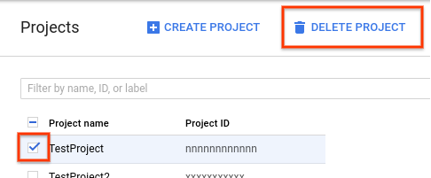
To delete a project, do the following:
- In the Cloud Console, go to the Projects page.
- In the project list, select the project you want to delete and click Delete project.
- In the dialog, type the project ID, and then click Shut down to delete the project.
What's next
- Learn more about AI on Google Cloud
- Learn more about Cloud developer tools
- Try out other Google Cloud features for yourself. Have a look at our tutorials.